The final production stage is a series of tests aimed at measuring the specified output parameters and demonstrating them to representatives of the customer. Gyrotrons and gyrotron complexes can be performed only in the laboratories, where highly specialized equipment and qualified personnel are available.
The experimental site of GYCOM Ltd. includes, in particular, two stands for testing gyrotron complexes. Stand 1 was designed and is used to test preproduction and deliverable gyrotron complexes manufactured within the framework of the ITER Project. Stand 2 is general-purpose and is used to test all kinds of gyrotrons, since its equipment can be tuned to fit different tasks. The both stands are located in the adjacent rooms in the same building and can be connected to common high-voltage power supplies and communication lines. Each stand consists of several zones, including the control room, the operating chamber, high-voltage power supplies, and auxiliary areas.
| |
|
 |
|
|
|
|
|
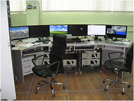
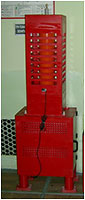
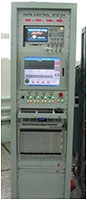
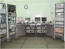
The control room (see Figs. 1 and 2) houses gyrotron control units, working places of operators, auxiliary power supplies, and interlock controls. Each stand is equipped with its own interlock system to prevent application of high voltage, while people stay in the operating chamber, as well as a failure of the gyrotron during electric breakdowns and other emergencies.
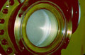
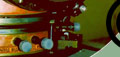
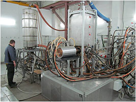
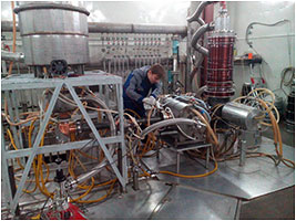
The equipment in the operating chamber (see Figs. 3 and 4) includes the gyrotron installed in a magnet, a microwave absorbing load, a microwave transmission line connecting the gyrotron and the load, the cooling system pipeline, and the system for high-vacuum evacuation of the transmission line and the load. Cables of the high-voltage power supplied, measuring instruments, and protective devices are connected to the gyrotron. The water cooling system is equipped with temperature and water consumption sensors to control the produced power. During tests of high-power long-pulse and continuous-wave gyrotrons, the transmission line and the load are evacuated continuously to increase the level of microwave breakdown intensity in the waveguide line and protect the gyrotron in the event of a microwave discharge.
 |
|
|
|
|
|
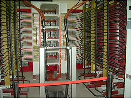
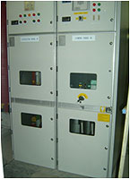
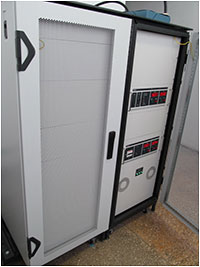
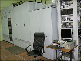
Each stand has the complete set of power supplies (PS) required for operation: high-voltage cathode and anode PS, heater PS, electric-discharge pump PS, and power supplies of the correcting electromagnetic coils and the protection system. Two high-power cathode sources are stationary and can be switched to feed any of the two stands. The other power supplies are mobile, provided in several sets, and can be delivered as components of gyrotron complexes, on customers’ request. For initial training of gyrotrons and operation in pulsed regimes, a Russia-made “Victoria” pulsed power supply is used. It has the following parameters: a voltage of up to 80 kV, a current of up to 40 A, and a pulse duration of up to 3 s. Its photo is shown in Fig. 5. A cathode power supply manufactured by the Institute of Plasma Physics of the Chinese Academy of Sciences (ASIPP, Hefei, China) shown in Fig. 6 is used for operation in the long-pulse regime (3 s – 1000 s) producing a voltage of up to 60 kV and a current of 50 A at an on-time of up to 1000 s. This is an up-to-date digitally controlled power supply with the possibility of remote operation. Currently, its specifications ensure performance of full-scale tests under all available contracts.
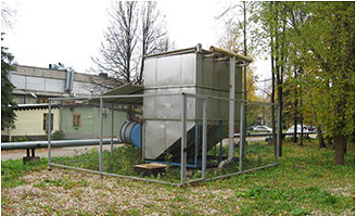
The auxiliary structure of the test stands are primarily water supply contours. Since gyrotron complexes are cooled with distilled and deionized water and have an energy consumption of up to 2.5 MW x 1000 s, the stands are provided with a supply of pure cooled water with a total consumption of up to 200 m3/h. The water is purified by a special system based on reverse osmosis. A special small-size cooling tower with a buried 50 m3 tank was built for water cooling (see Fig. 7).
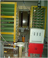
The third stand is being built for tests of low-power continuous-wave gyrotrons and technological complexes based on them. It will be equipped with its own set of high-voltage power supplies with voltages of up to 25 kV and a current of up to 2.5 A similar to those shown in Fig. 8.